

FLOMC
Request Information
FLOMC

Observe equipment through a defined panel location while keeping its specified boundary in place.
Review panel retention, frame connections and the conditions for removal. Required protective functions must be specified and validated for the application.
Start with what needs to be observed and where the observer will stand.
Define the panel, frame and attachment requirements against the functions assigned to that part of the equipment boundary.
Separate routine observation from tasks that require an access opening.


Keep the viewing task and the specified boundary requirements together when reviewing the assembly.

Identify the operating position, viewing target and equipment states in which observation is needed.
Observer / Target / Operating state

Record the functions assigned to the viewing area and the conditions under which the equipment boundary must remain closed.
Specified function / Closed state / Interfaces

Define supported edges, retaining parts and fixing positions. Review their connections to the frame and surrounding equipment.
Panel support / Retaining parts / Fixings

Clarify whether the panel is fixed or removable, who may remove it and what equipment conditions apply before opening the area.
Access conditions / Removal route / Responsibilities

Agree which checks and evidence are needed after installation or replacement, and identify the person responsible for acceptance.
Inspection / Evidence / Acceptance

A fixed viewing area supports observation through the panel. If a task requires a door to open or a panel to be removed, define that as a separate access condition.
Record who may open the area, the equipment conditions required before access and the checks needed before returning it to use.

Keep routine viewing separate from tasks that require opening or removing the panel. Confirm the supplied component scope and responsibility for the surrounding equipment. The machine manufacturer or integrator remains responsible for the equipment risk assessment and final validation.
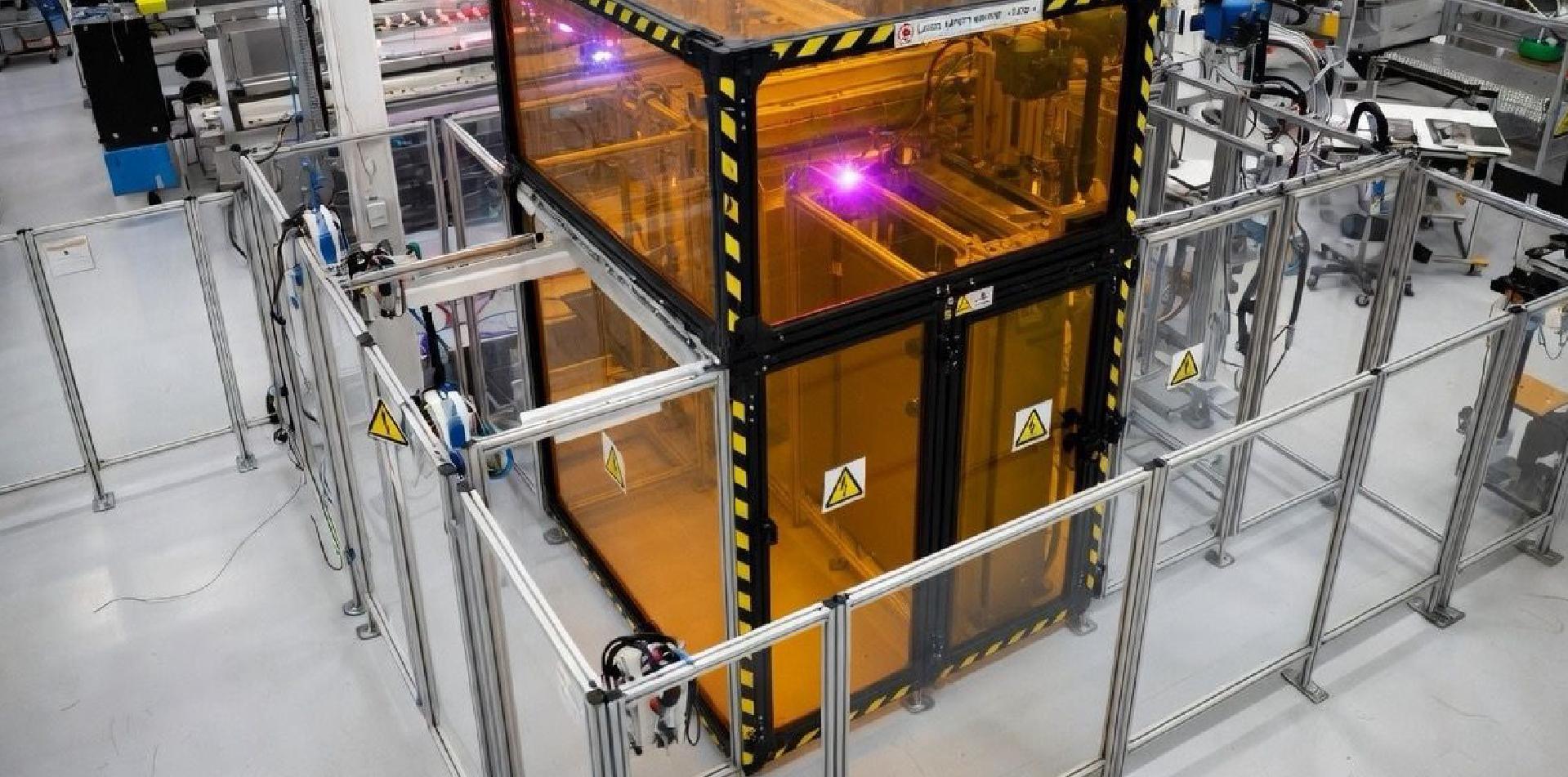
Document expected conditions at the viewing area. Review material compatibility alongside panel thickness, the frame, seals and attachment details.
Material data alone does not establish the performance of an installed viewing assembly. Identify any evidence gaps, further checks and the party responsible for acceptance.


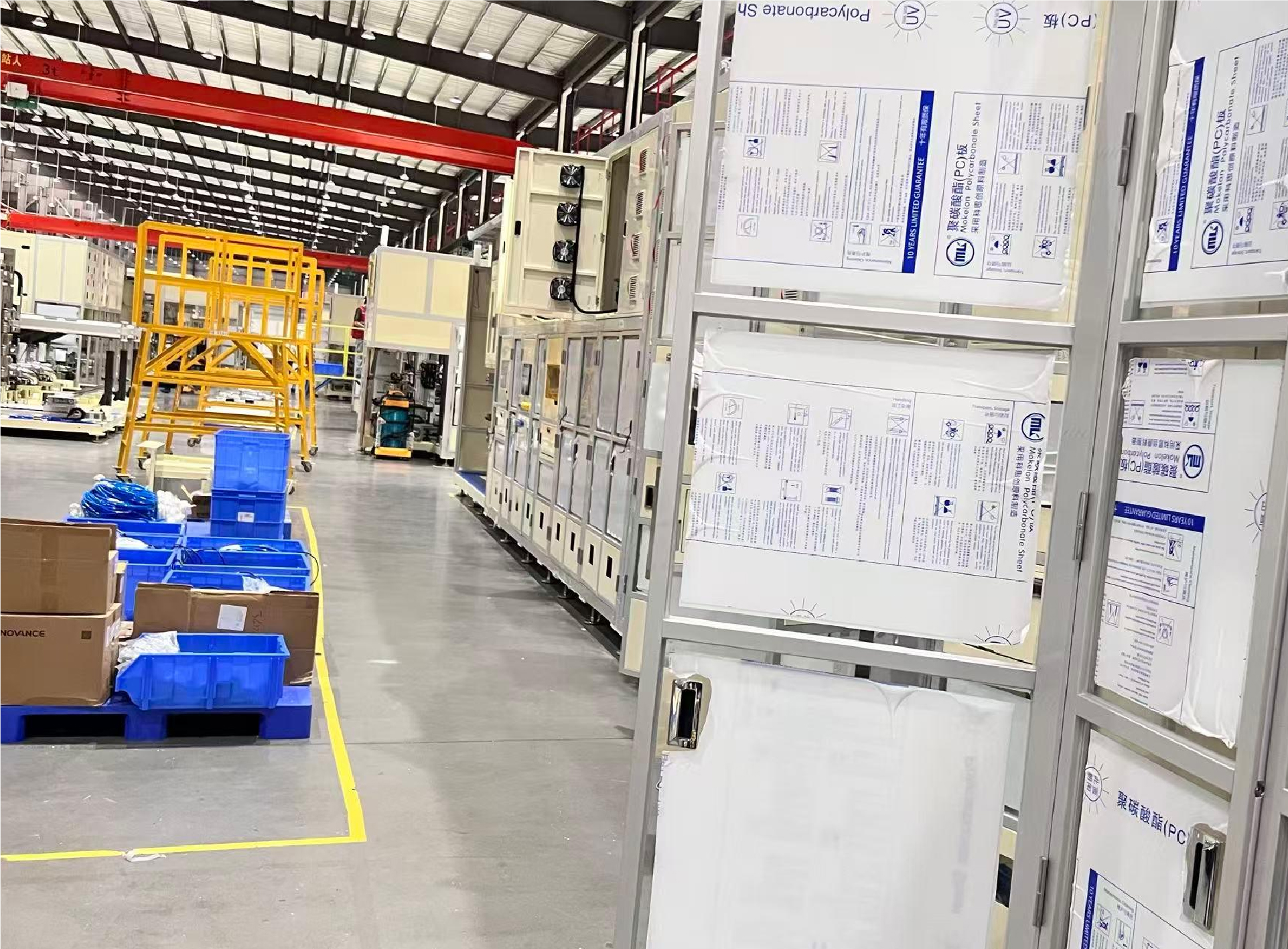
Share the equipment layout, opening drawing and observation position.
Include the functions assigned to the boundary, operating conditions and any existing evidence.
Use the review to identify unresolved details and agree the next engineering checks.
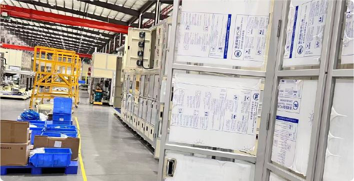
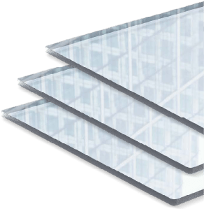

Provide material candidates, panel dimensions and the expected temperature, cleaning and process conditions for compatibility review.

Describe the observation task, lighting, permitted surface condition and cleaning method. Specify any optical or surface requirements that need evidence.
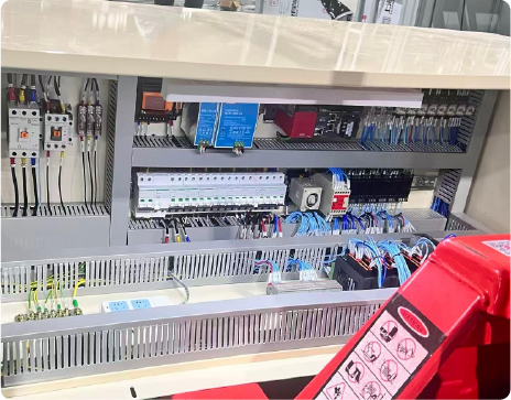

Supply drawings for edges, cut-outs, holes and interfaces. Agree dimensions and tolerances before selecting fabrication and assembly steps.
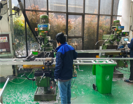

Show panel support, retaining parts, frame connections and seals. Define the component supply boundary and who accepts the installed arrangement.
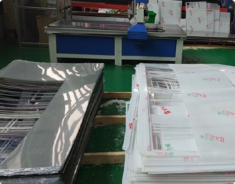

Identify existing equipment constraints, removal procedures and checks after replacement. Confirm the integrator and the evidence required for final acceptance.
Use reference images to discuss viewing positions, surrounding frames and installation context. Confirm the requirements and evidence for your own configuration.
Share the opening drawing, observation position and specified boundary requirements.
Include panel retention, operating conditions and the procedure for opening or removal.
FLOMC can review the proposed component scope and help identify the information needed for the next engineering discussion.


English

German

Italian

Spanish