

FLOMC
Request Information
FLOMC

Viewing panels, frames and mechanical enclosure components for laser equipment.
Specify the laser exposure, protective evidence and installation interfaces before material selection.
Viewing panels, frames, and enclosure components for laser equipment. Protective material selection depends on the laser wavelength, exposure conditions, and documented performance of the selected panel.

FLOMCTECH Customizes laser shielding panels for equipment openings, doors, viewing areas, and local protection boundaries, balancing protection, visibility, fit, installation, and replacement.

FLOMC innovates laser protection structures for industrial equipment, coordinating shielding, visibility, access, fabrication, and installation around the machine layout.
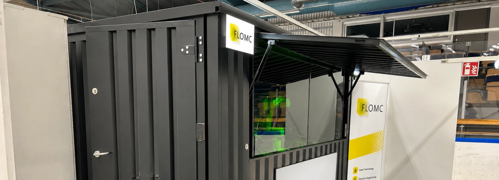
Coordinate laser enclosure panels, viewing openings and access interfaces around defined exposure and the equipment builder’s system validation requirements.
In laser equipment, the transparent area is rarely an isolated part.
It sits inside frames, doors, shielding zones, machine movement, cleaning routines, and operator observation.
FLOMC supplies the agreed material and mechanical components. Laser risk assessment, safety controls, interlocks and final system validation remain with the equipment builder or integrator.
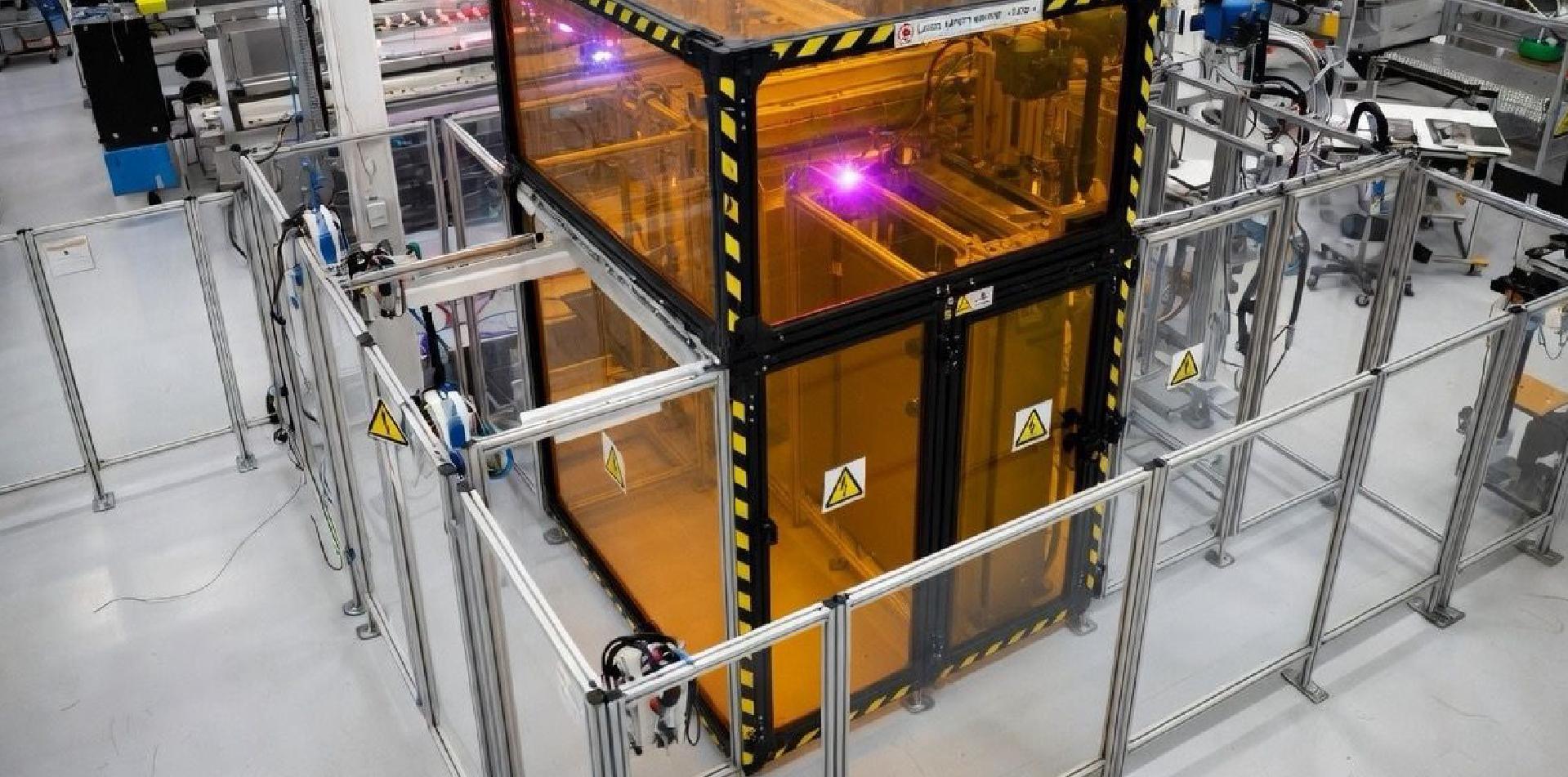
Laser processing systems often bring several transparent areas into the same equipment environment.
The images illustrate component forms, not completed projects or verified laser ratings. Confirm protective evidence for the intended wavelength and exposure.
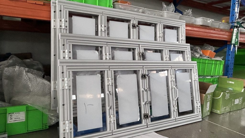
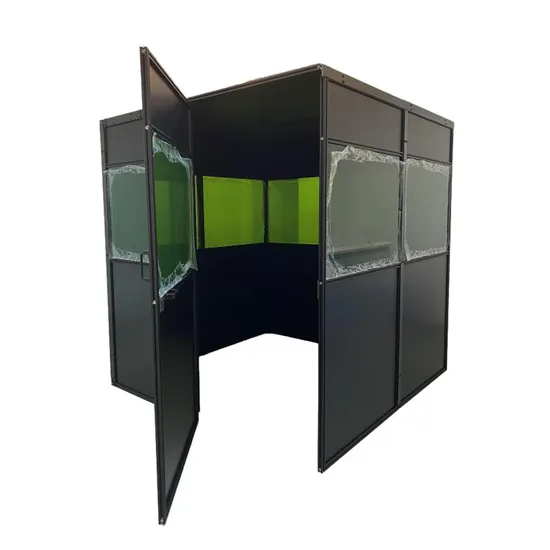

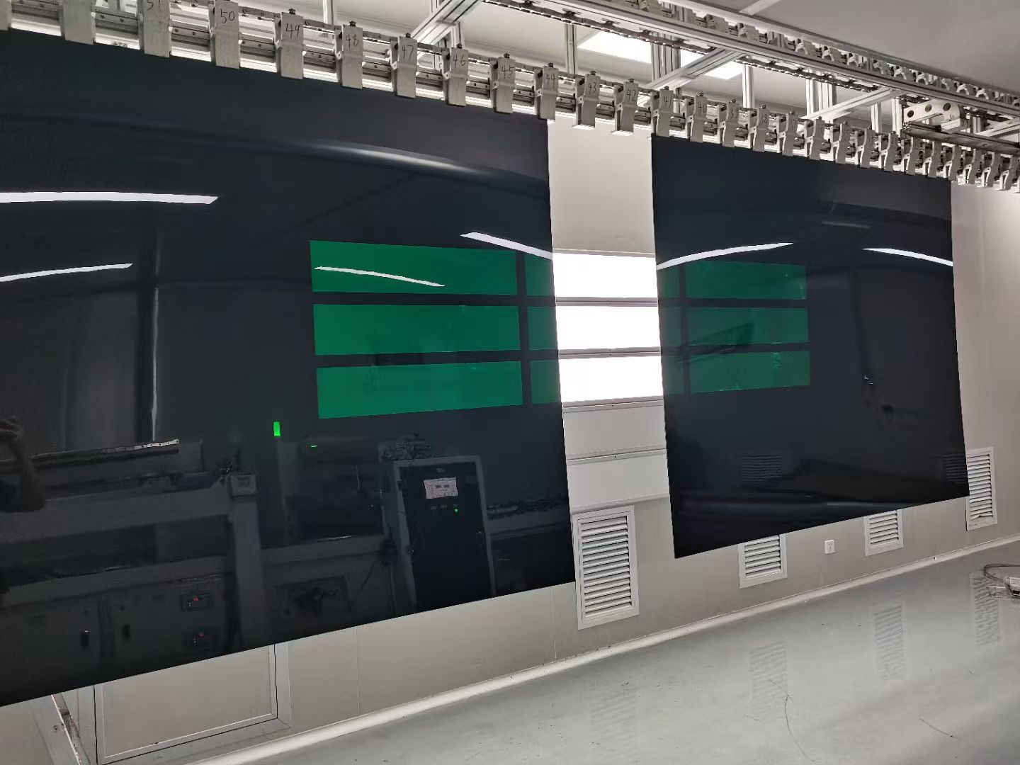
Review wavelength-specific material evidence with panel geometry, retention, joints and mounting interfaces.
Agree fabrication, cleaning and replacement requirements for the selected construction; color or transparency alone does not establish laser protection.
Transparent material selection
Documented wavelength and exposure requirements
Coating and surface stability
Permitted fabrication for the selected material
Frame and enclosure assembly
Installation and maintenance access

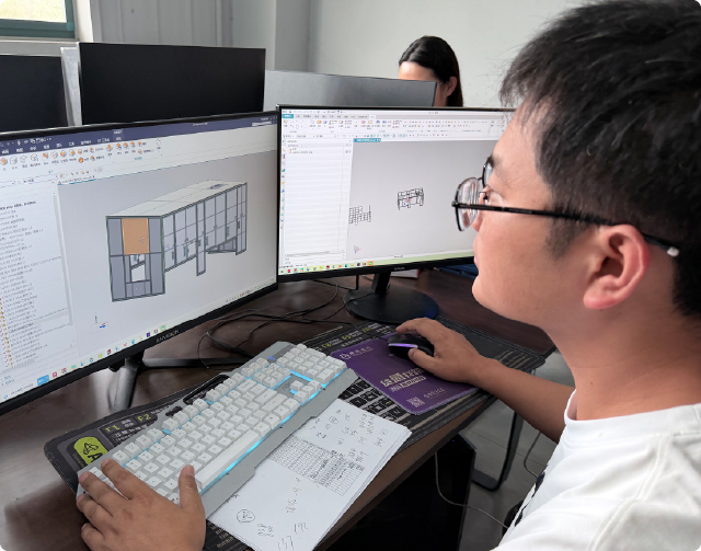
These photographs illustrate mechanical assembly and enclosure arrangements, not documented customer projects.
Discuss the panel, frame, access and replacement interfaces for your equipment.
Images do not establish laser attenuation, exposure resistance or complete-system compliance.
Illustrative assembly detail: profile connections are defined for the agreed frame and component geometry.
Illustrative enclosure arrangement: panel retention, edges and access must match the specified protective design.
FLOMC can support your project from material selection, surface performance, panel processing, and structural development to OEM integration and installed-site adaptation.
Share the equipment context, viewing requirement, protection concern, or existing structure you are working with. We can help define the next practical direction.

English

German

Italian

Spanish