

FLOMC
Request Information
FLOMC
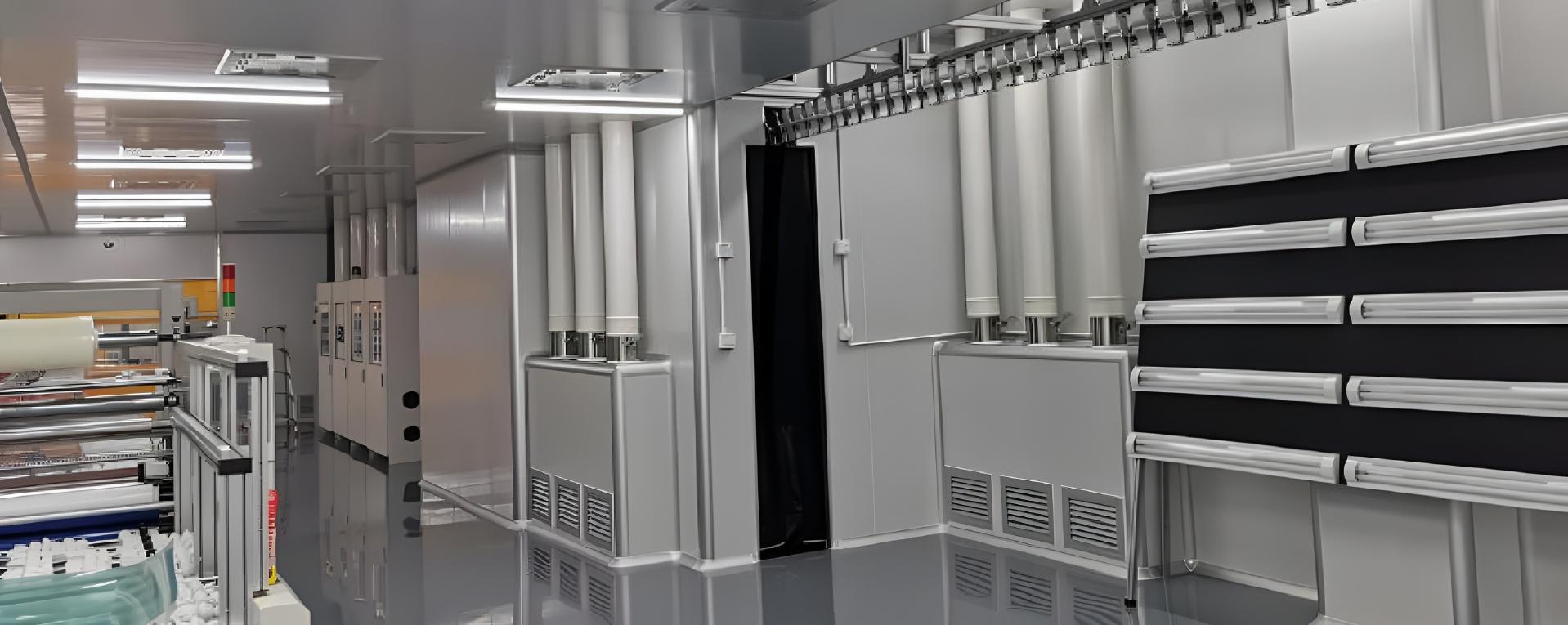
Clear viewing within a defined static-control plan. Coordinate transparent panels, frame interfaces and cleaning requirements around the equipment and its ESD control plan. Verify performance for the selected material and installed assembly.
An observation panel is one part of the equipment design. Define the sensitive process, viewing position, material requirement, frame interface, cleaning method and verification plan.
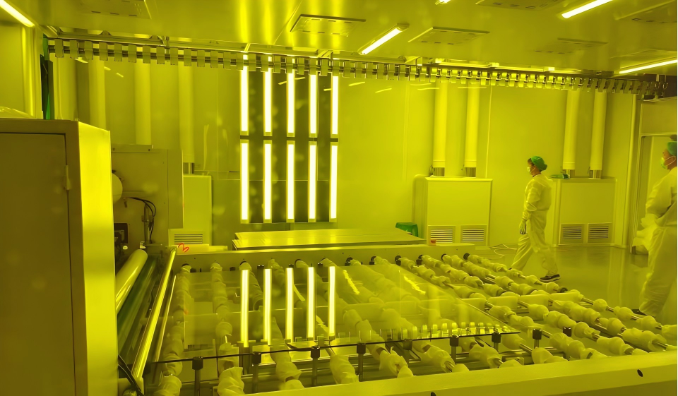
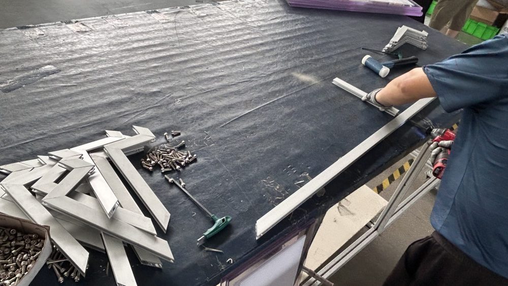
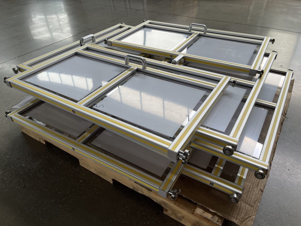
Review visibility, material behaviour and integration within the equipment ESD control plan.

Where visibility is kept inside the guarding or equipment boundary.

Where the transparent area meets profiles, covers, doors, or machine frames.

Where cleaning, abrasion, static, and long-term use start to show.

Where the viewing area has to fit the real equipment layout.
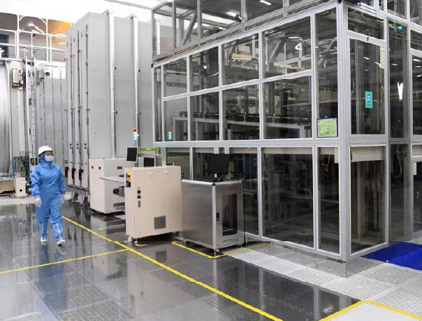
Observation windows, transparent doors and equipment covers need a coordinated specification. Start with the required viewing area and panel grade, then review supports, fasteners and any specified grounding connections.
A transparent panel alone does not establish an ESD-protected area or a cleanroom classification. The equipment owner defines and verifies the overall control measures.
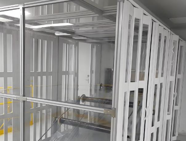
Define the panel-to-frame interface with the equipment team. Identify contact surfaces, coatings, seals and any specified bonding or grounding points; mechanical contact alone does not establish an electrical path.
After installation, confirm the viewing line, panel retention and service access. Verify specified electrical interfaces against the agreed method and acceptance criteria, and record the results. Define cleaning, inspection and re-verification after panel replacement in the equipment documentation.
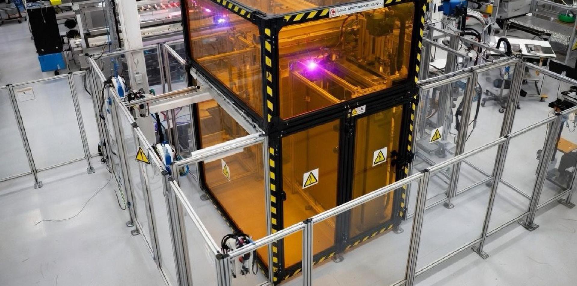
Define the material requirements for the actual service conditions.
Request grade-specific data and agree on testing conditions. Static-control behaviour, durability and service life must not be assumed from appearance or a generic material name.
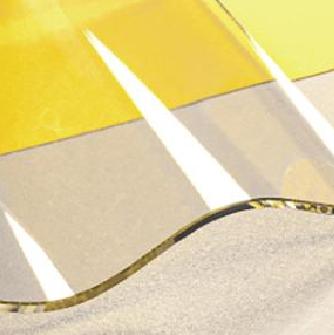
A viewing area may begin as a transparent panel.
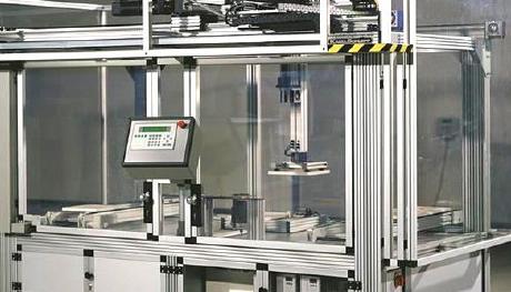
On the equipment, it becomes part of the frame, guarding boundary, access position, cleaning routine, and inspection logic.
That is why FLOMC reviews industrial viewing structures through visibility, material surface, frame contact, access, and installation together.
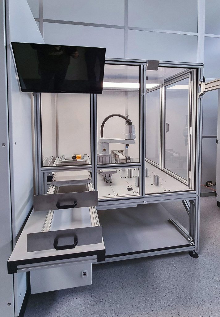
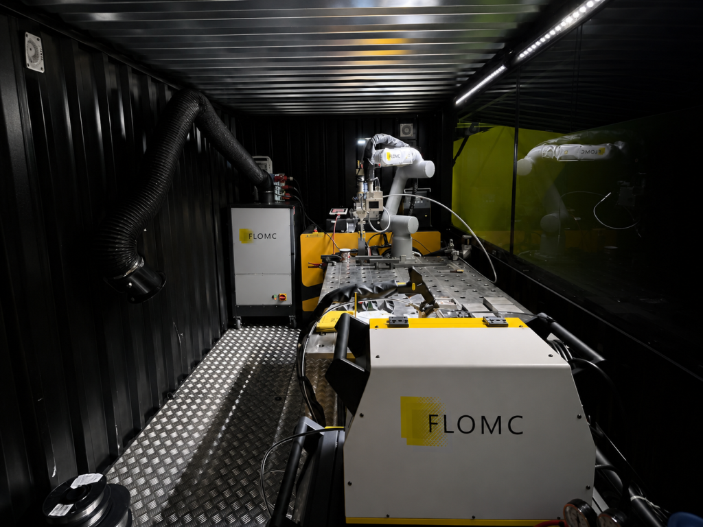
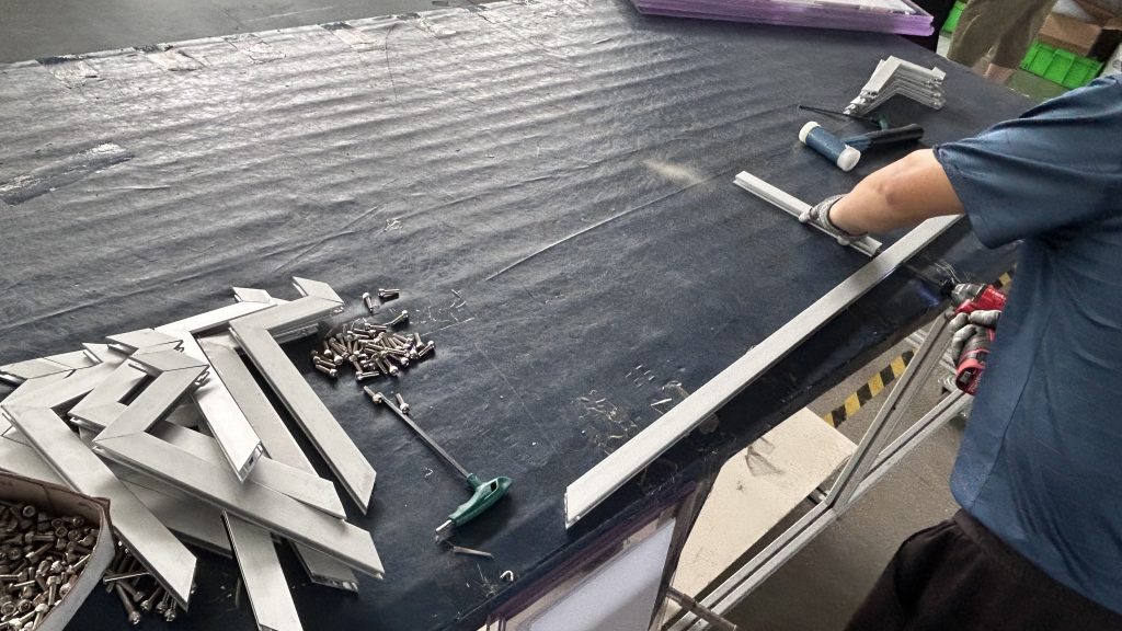
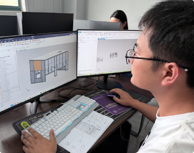
FLOMC can support your project from material selection, surface performance, panel processing, and structural development to OEM integration and installed-site adaptation.
Share the equipment context, viewing requirement, protection concern, or existing structure you are working with. We can help define the next practical direction.

English

German

Italian

Spanish