FLOMC
Request Information
FLOMC
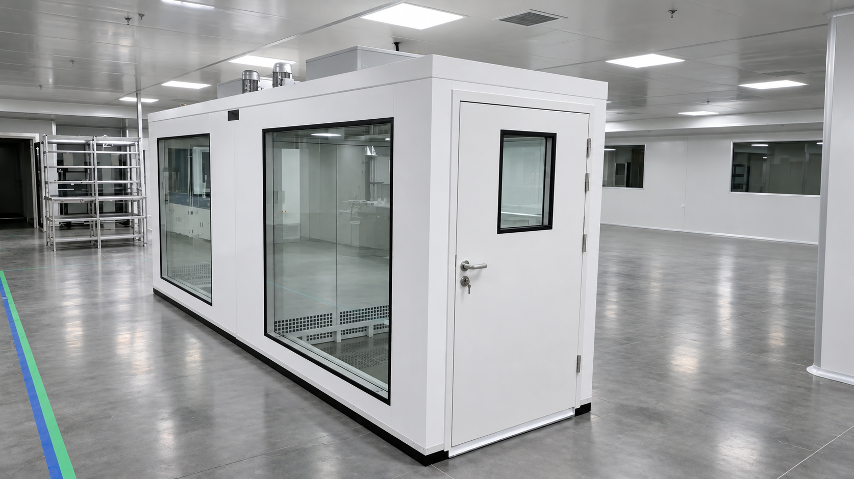
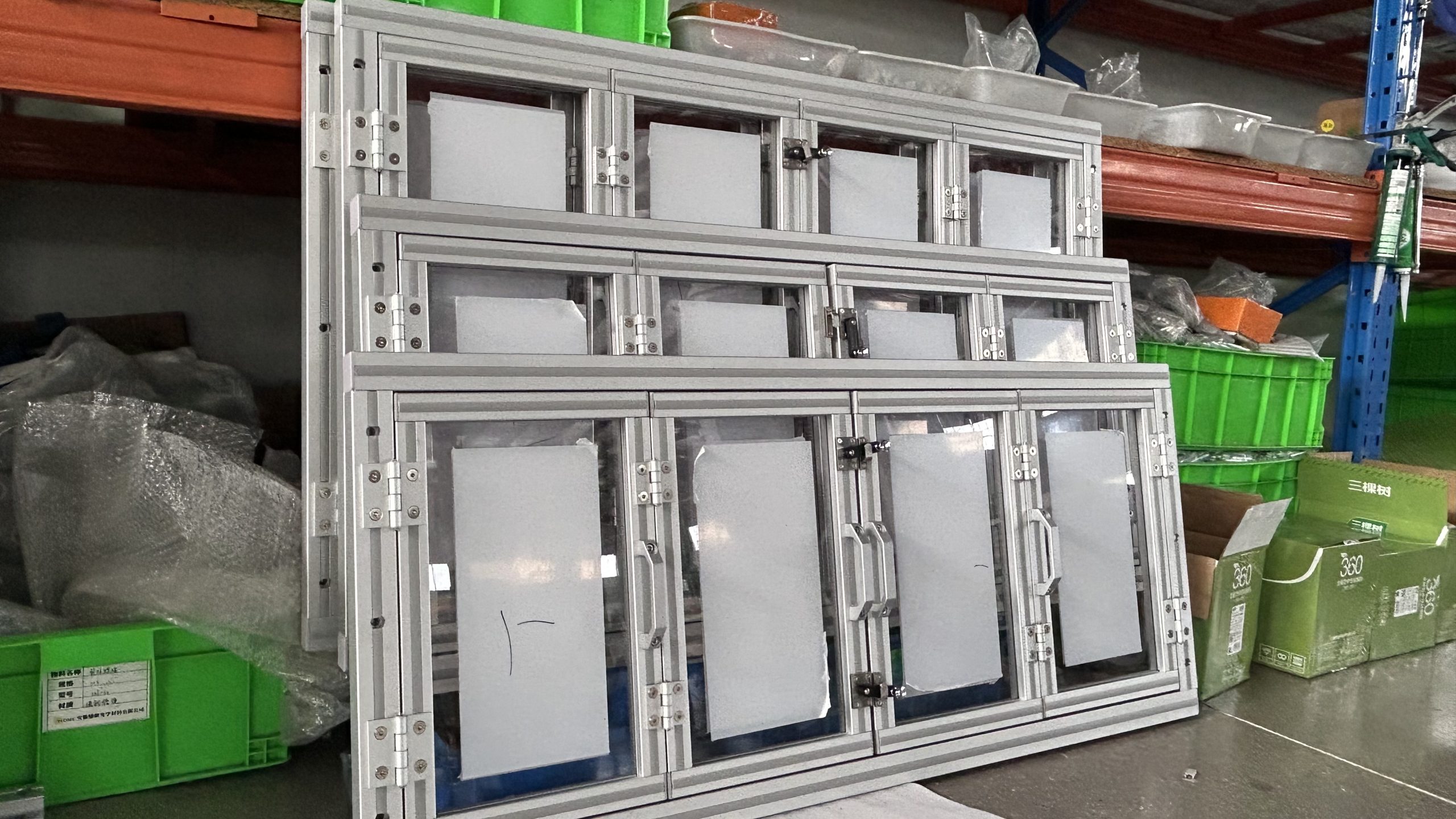
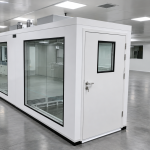
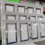
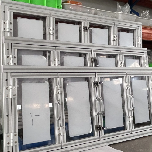
FLOMC works with equipment manufacturers and integrators on viewing windows for machine doors, enclosure panels and inspection openings.
Discuss panel-only supply, framed modules or replacement parts, with dimensions and mounting details defined around your equipment.
The mounting opening is the equipment cutout. The clear viewing area is the unobstructed view after fitting. Overall size describes the outside of the complete frame.
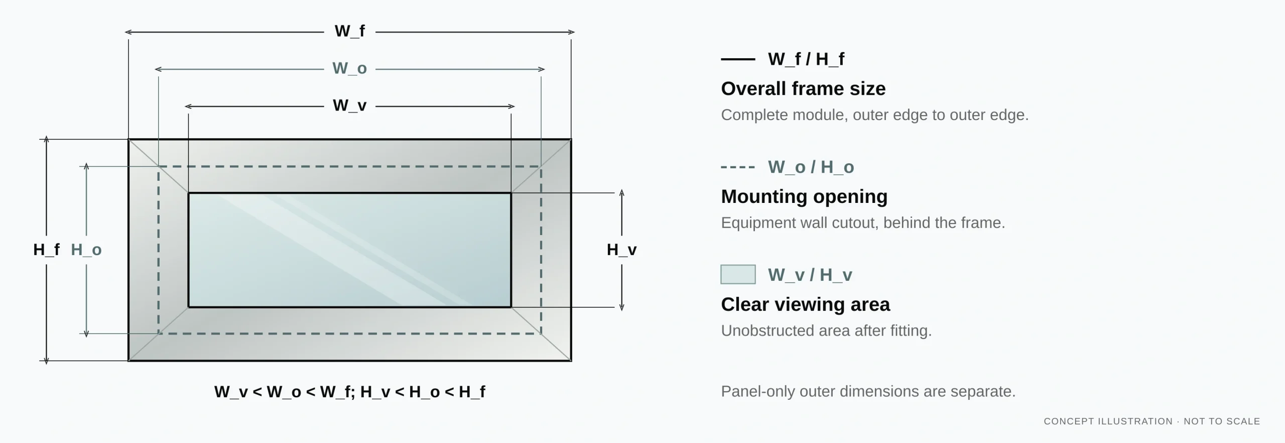
Mounting Opening, Clear View and Overall Frame Size
View full-size dimension diagram (zoom in)
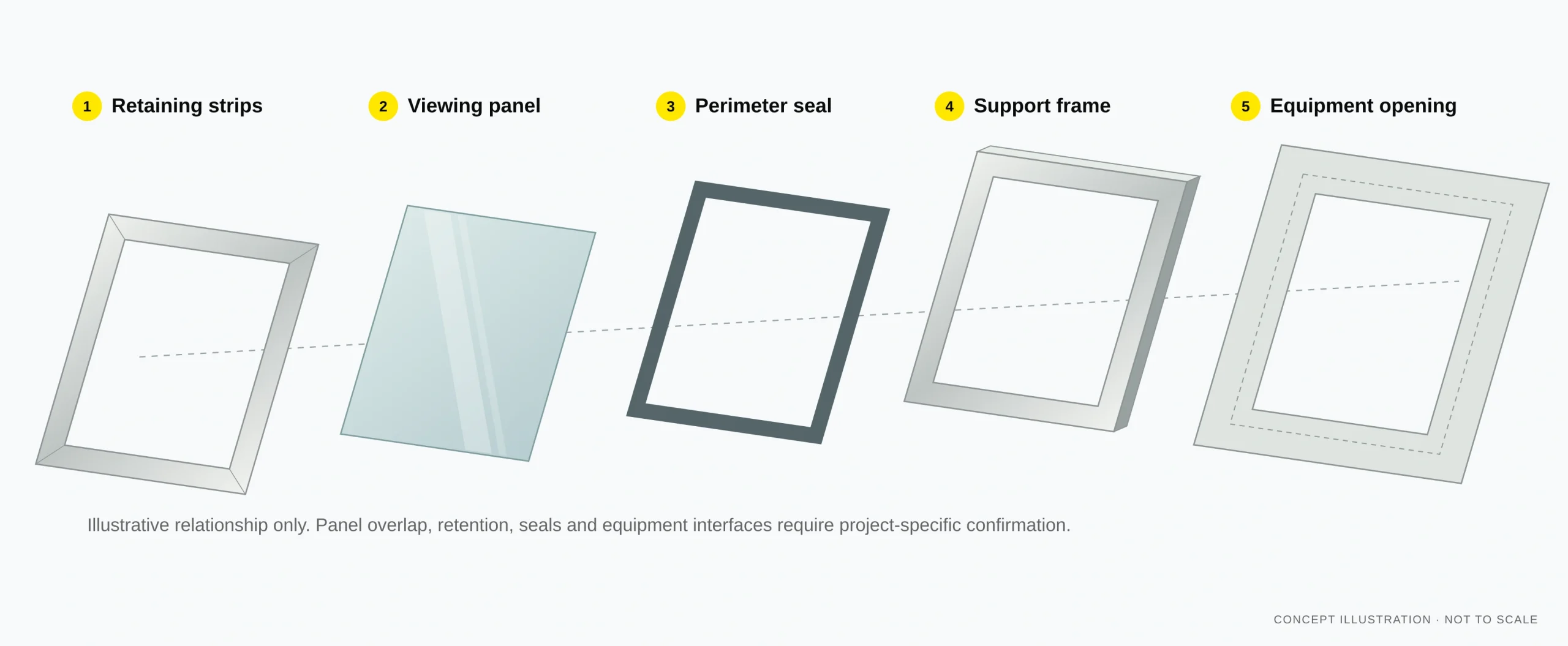
Confirm the supporting structure, retaining edges, hole pattern, seal path and accessible fitting side. Specify flush or surface mounting and identify the parts required in your quotation.
Allow space to remove the panel and fasteners during maintenance. Confirm the fitting side, replacement path and which frame or retaining parts will remain in place.
View full-size assembly diagram (zoom in)
Start with a fixed viewing panel, a framed module or a replacement window. Define the drawing and supply boundary for your equipment.

Processed panels for defined equipment openings, with material, outline and fixing details agreed.
Get a Quote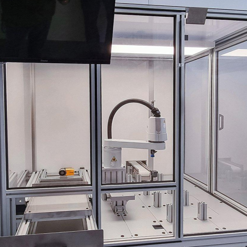
A coordinated panel and retaining frame, with seals, fasteners and mounting interfaces defined in the quotation.
Get a Quote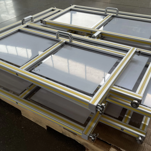
Replacement panels or modules matched to verified openings, retained parts and current operating conditions.
Get a QuoteDefine dimensions, materials and interfaces for the selected supply format.
| Requirement | Input | Unit / Format | Panel Supply | Framed Module |
|---|---|---|---|---|
| Mounting opening | Equipment cutout | Dimensions with units | Panel outline | Frame interface |
| Clear viewing area | Required view | Dimensions with units | Unobstructed area | View after retention |
| Overall size | Outside envelope | Dimensioned drawing | Panel size | Outer frame size |
| Material | Operating conditions | Grade designation | Selected substrate | Panel and frame |
| Surface | Cleaning and exposure | Cleaning notes | Specified treatment | Compatible finishes |
| Mounting | Fixing arrangement | Interface drawing | Holes and edges | Retention and seals |
Supply scope is agreed from the drawing and equipment interfaces.
| Format | What to Send | Interfaces | Supply Scope |
|---|---|---|---|
| Fixed window | Opening and panel drawing | Retaining detail | Processed panel |
| Framed module | Assembly dimensions | Frame and fixing | Agreed module |
| Replacement | Photos and measured part | Retained components | Panel or module |
Dimensions, tolerances and performance requirements must be agreed for the specific construction.
Send your drawing, quantity and operating conditions to review the window specification.
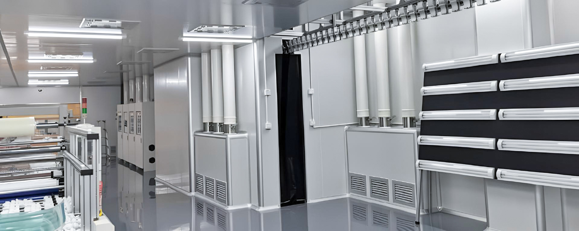
Connect the material, processed panel and mounting details in one agreed supply scope.
Review visibility, cleaning, temperature and exposure for the selected grade.
Define outlines, holes, edges and the viewing area before manufacture.
Review coating, cleaning and appearance needs against the chosen construction.
Confirm frame, seals, retention and installation responsibilities in the supply scope.
Define the viewing opening for new equipment or a replacement part. Review the surrounding frame, installation access and service conditions.
Coordinate the opening, viewing position, panel retention and service access while the equipment layout is being defined.
Confirm measured interfaces, retained parts, cleaning conditions and the replacement path before specifying a new panel or module.
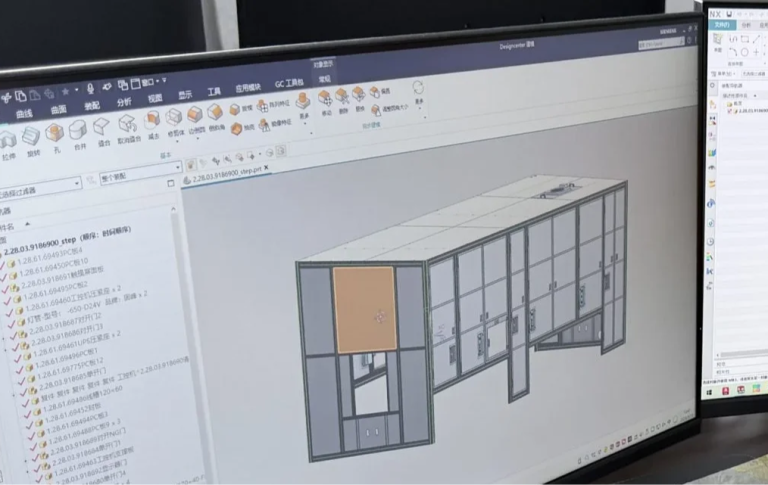
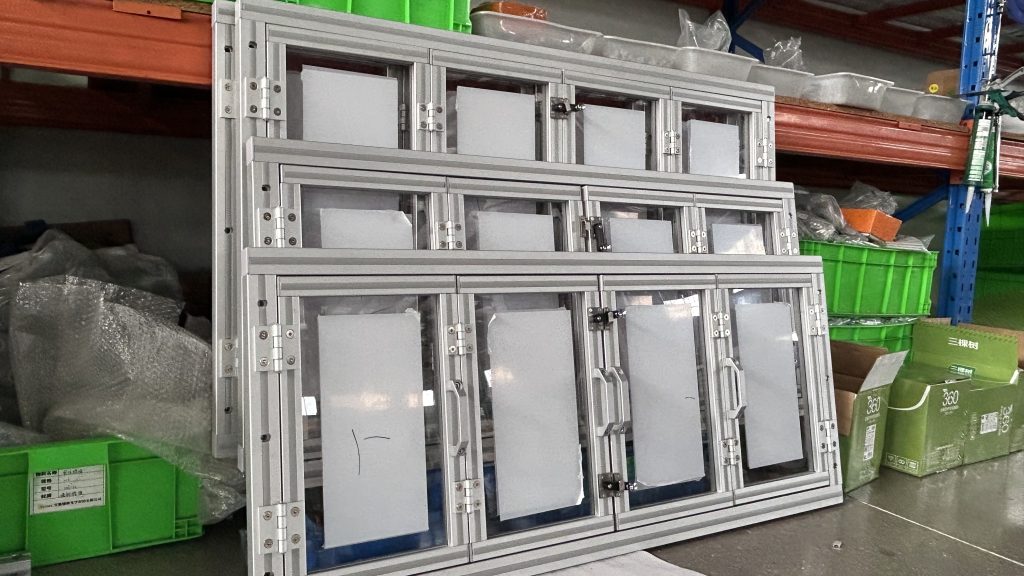
Framed viewing window assembly
Start with the opening and installation details. Use these answers to prepare your quotation request.
The opening is the equipment cutout. The clear viewing area is the unobstructed view after fitting, while overall size measures the panel or frame. Provide all three dimensions separately and state what was measured.
Specify panel-only supply and include the existing retaining and sealing details. For a framed module, identify the frame, seal and fixing items to include. The quotation should list the agreed scope.
Prepare front and rear photos, panel and frame dimensions, thickness, hole positions and fixing method. Include the seal profile if known and the accessible removal side. A photograph alone cannot confirm fit.
Share visibility needs, operating temperature, chemical exposure and cleaning agents. Confirm material and surface treatment before selecting a cleaning method. Plan access for inspection and replacement.
Provide the hazard, operating conditions and required standard or rating. For laser use, include wavelength and the protection specification. Performance claims need evidence for the relevant configuration; a general viewing-window drawing establishes no protective rating.
FLOMC can support your project from material selection, surface performance, panel processing, and structural development to OEM integration and installed-site adaptation.
Share the equipment context, viewing requirement, protection concern, or existing structure you are working with. We can help define the next practical direction.

English

German

Italian

Spanish