

FLOMC
Request Information
FLOMC
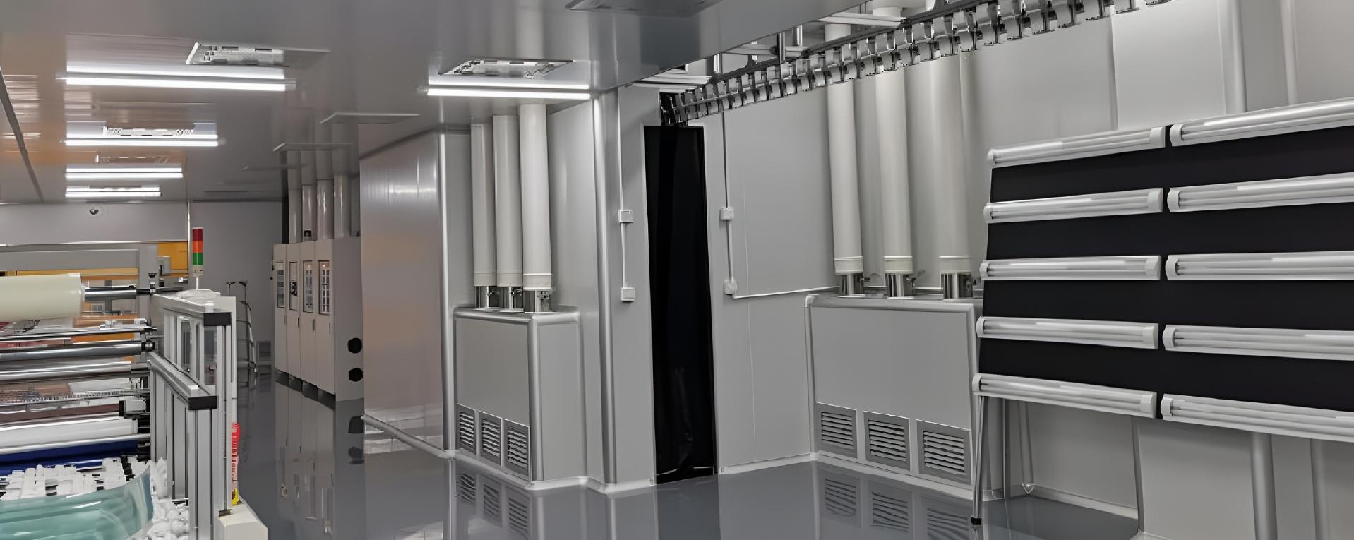
Define the viewing panel, frame and access interfaces around the hazards identified for your equipment.
FLOMC supports processed components and mechanical assemblies within an agreed project scope.
Use the equipment risk assessment to define what the boundary or viewing assembly must do. Record the process, operating modes, exposure conditions and people who need access.
Agree measurable requirements before selecting panels, frames or openings. Record the required evidence and who is responsible for each part of the project.
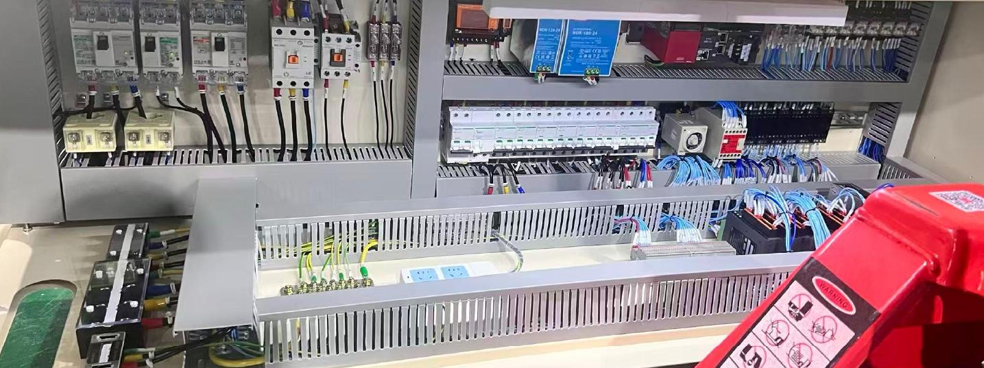
Specify each interface against the agreed equipment requirements. A panel or frame on its own does not establish complete-system protection.

Where visibility is kept inside the guarding or equipment boundary.

Where the transparent area meets profiles, covers, doors, or machine frames.

Where cleaning, abrasion, static, and long-term use start to show.

Where the viewing area has to fit the real equipment layout.
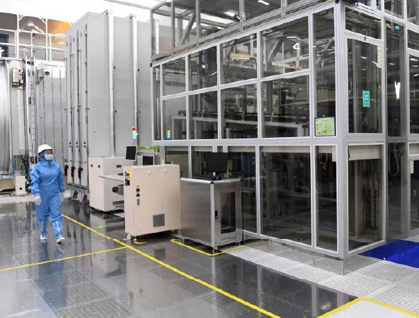
Define the processed panel, supporting frame, retaining parts, seals and access hardware included in the quotation. Confirm dimensions, fixing points and connections to the surrounding equipment.
The equipment builder or integrator specifies safety distances, interlocks and control integration, and validates the complete installation. Any fire, explosion, electrical arc-flash or radiation-protection requirement needs a separate technical assessment and supporting evidence.
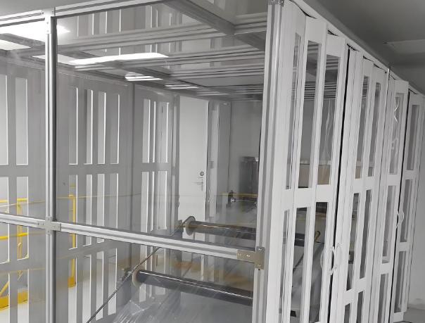
Check the layout for normal operation, loading, adjustment, cleaning and maintenance. Define these inputs with the equipment owner.
Review the installed arrangement, including joints and adjacent equipment. Access procedures, energy isolation and operating instructions remain part of the equipment owner or integrator's safety arrangements.
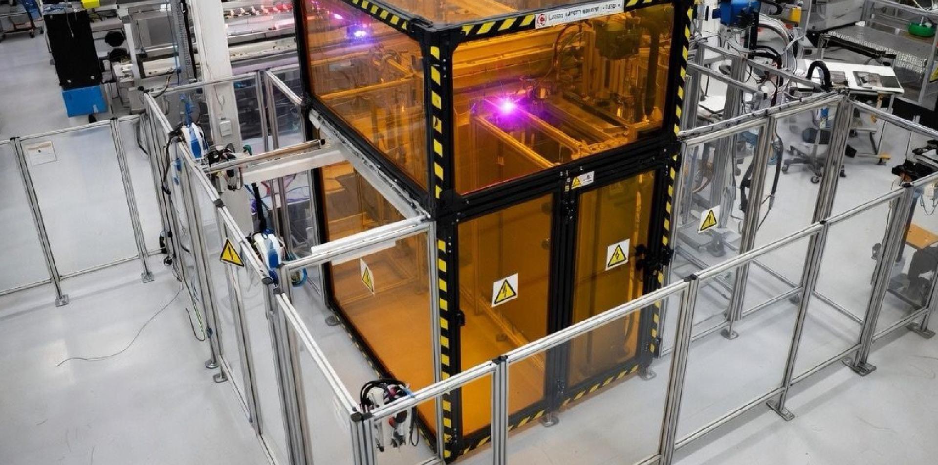
Request evidence for the selected material, thickness, fabrication and mounting arrangement against the project requirements.
The material families below are discussion options, not protective ratings for an installed assembly. Transparency, a hard coating or static-control properties alone do not establish suitability for a hazardous environment. Confirm the complete construction and the required validation before use.
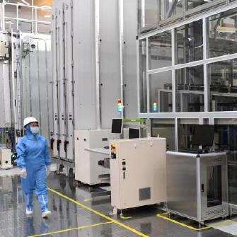
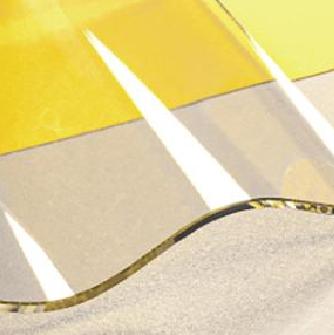
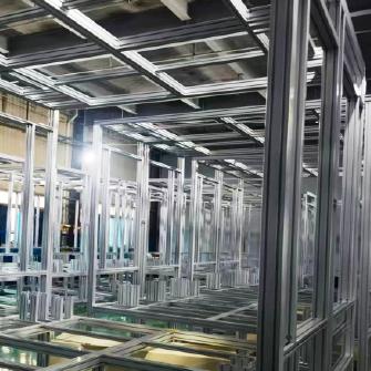
A viewing area may begin as a transparent panel.
On the equipment, it becomes part of the frame, guarding boundary, access position, cleaning routine, and inspection logic.
That is why FLOMC reviews industrial viewing structures through visibility, material surface, frame contact, access, and installation together.
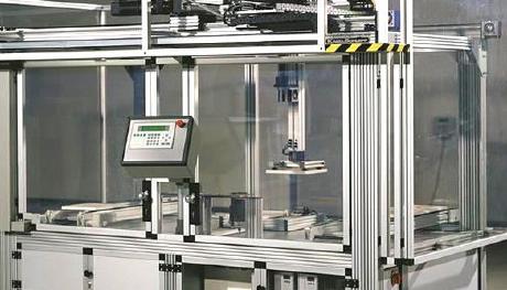
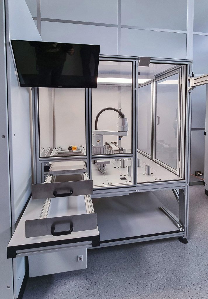
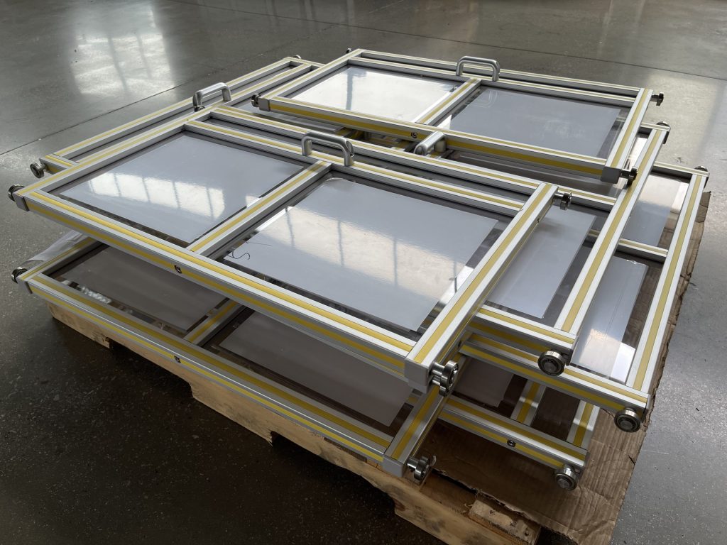
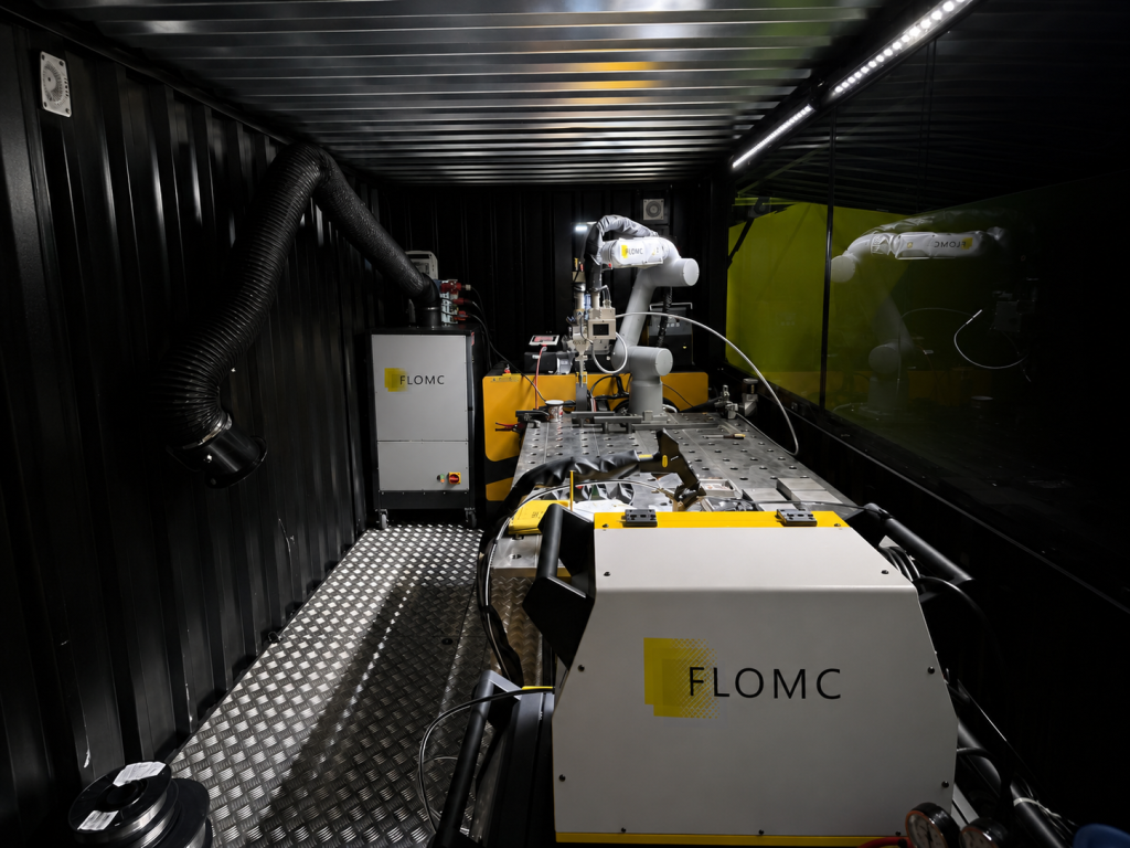
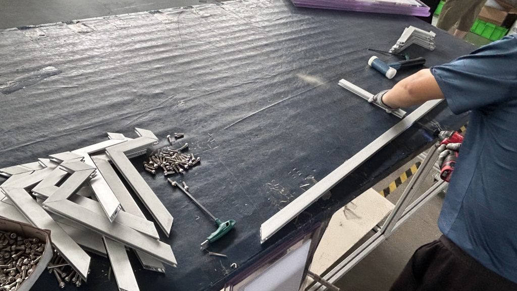
FLOMC can support your project from material selection, surface performance, panel processing, and structural development to OEM integration and installed-site adaptation.
Share the equipment context, viewing requirement, protection concern, or existing structure you are working with. We can help define the next practical direction.

English

German

Italian

Spanish