

FLOMC
Request Information
FLOMC
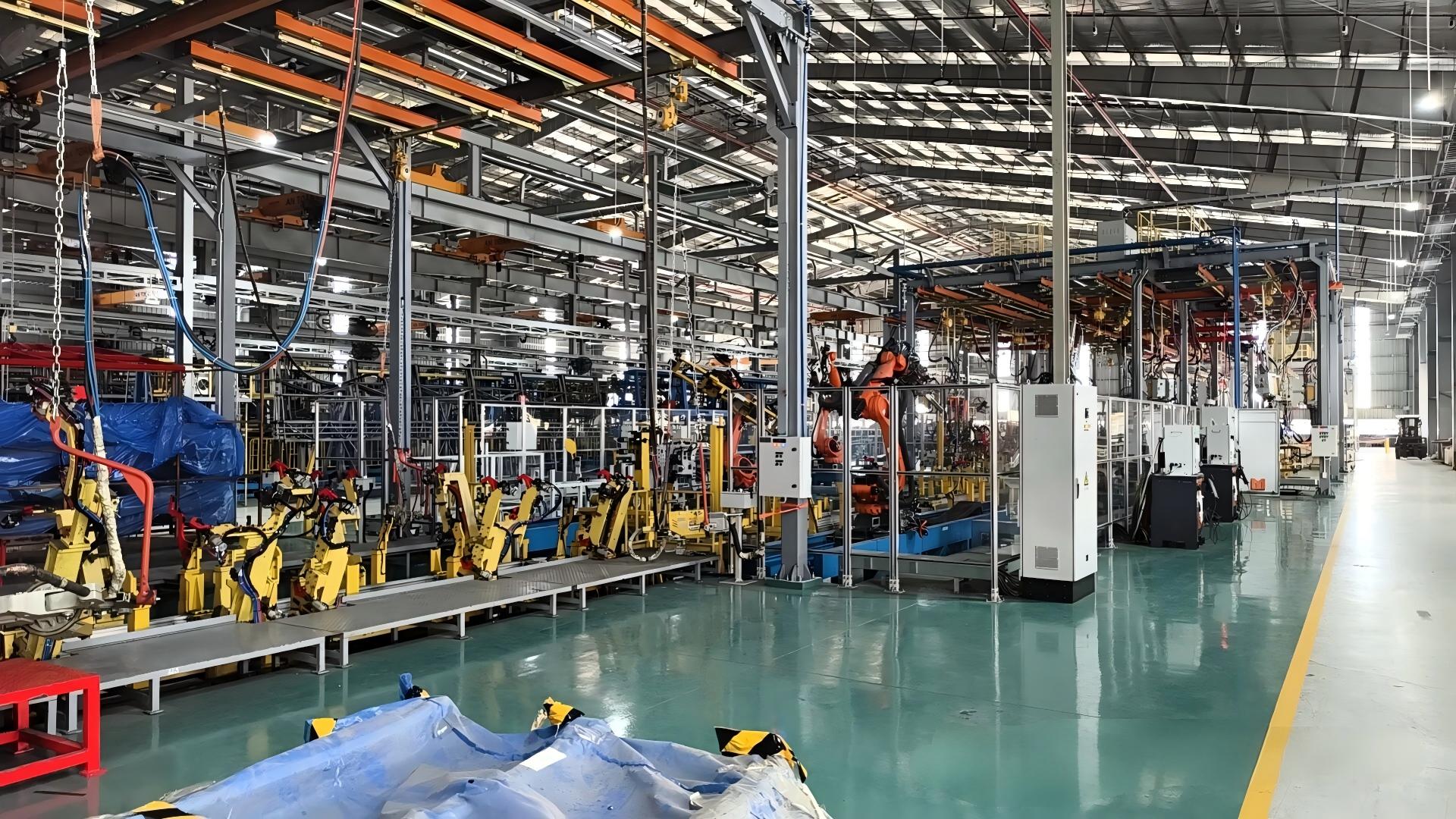
Frames, panels and access gates define the boundary around an automated line.
FLOMC coordinates the mechanical layout with loading routes, viewing positions and maintenance access.
Start with the equipment footprint and the routes around it. Coordinate fixed bays, access openings and viewing areas with the agreed line layout.
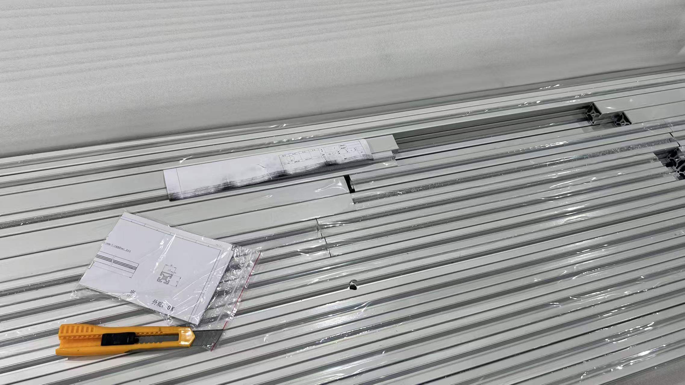
Agree how each part connects before manufacture.

Frame spans, panel sizes and fixing points follow the agreed boundary.

Opening size, swing direction and hardware follow the access plan.

Place transparent panels where the process needs to remain visible.

Confirm floor, machine and adjoining-frame connections.
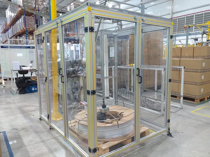
Place doors where operators load parts, technicians service equipment and larger components leave the line. Confirm opening dimensions, swing or sliding clearance, and nearby traffic routes.
Agree hinges, handles, stops and mechanical mounting provisions with the equipment builder. Any interlock selection, control integration and validation remain part of the builder or integrator's safety design.
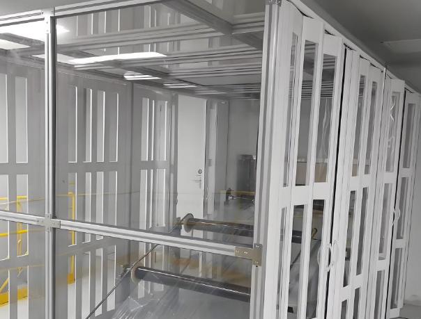
Place transparent sections where operators need to observe the line. Review these positions alongside access routes and the surrounding equipment.
The equipment builder or integrator defines the required boundary dimensions, openings and separation distances through the equipment risk assessment. Agree these inputs before detailing the mechanical layout.
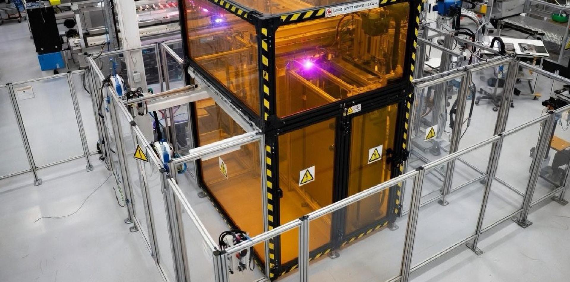
Select panel materials and surface finishes against the actual process, viewing task and mechanical requirements. Review the complete panel-and-frame arrangement.
The material families shown below are selection options, not ratings for an installed guard. Any required protective or electrical performance needs evidence for the selected construction and intended use. The equipment builder or integrator validates the complete guarding system.
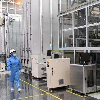
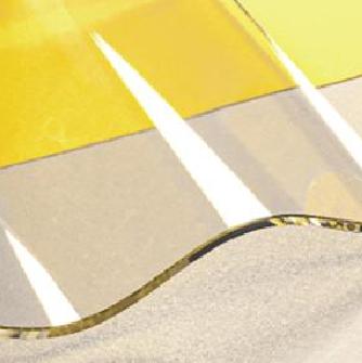
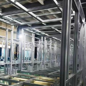
A viewing area may begin as a transparent panel.
On the equipment, it becomes part of the frame, guarding boundary, access position, cleaning routine, and inspection logic.
That is why FLOMC reviews industrial viewing structures through visibility, material surface, frame contact, access, and installation together.
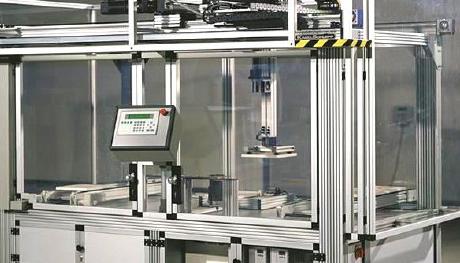
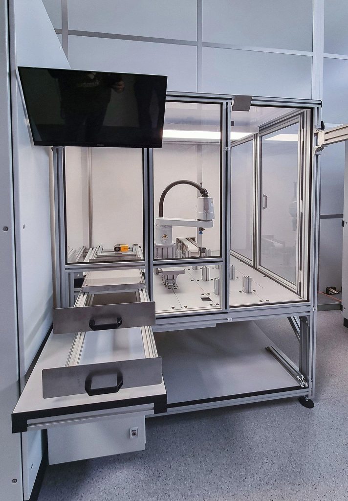
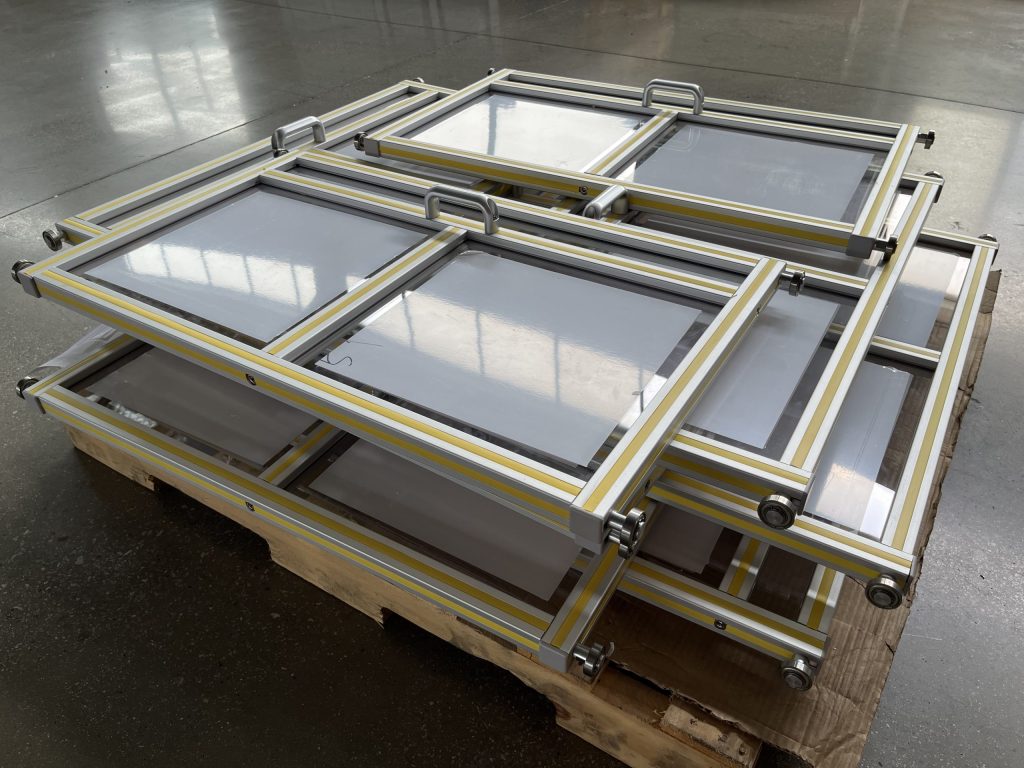
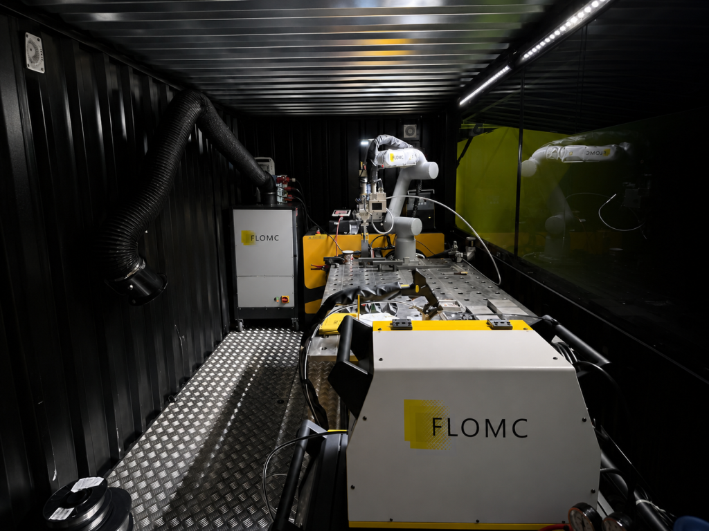
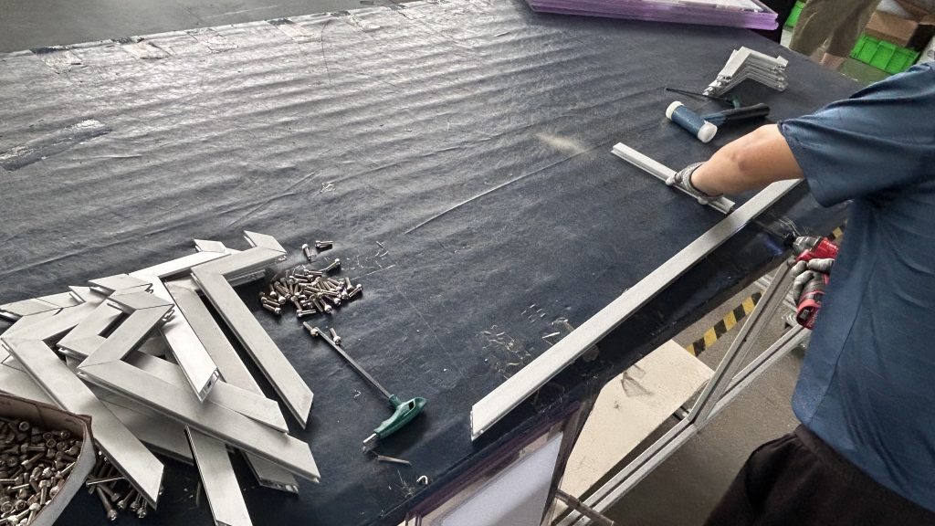
FLOMC can support your project from material selection, surface performance, panel processing, and structural development to OEM integration and installed-site adaptation.
Share the equipment context, viewing requirement, protection concern, or existing structure you are working with. We can help define the next practical direction.

English

German

Italian

Spanish